Exercise: Placing the Path Control Points and Curve
To begin the model
place four points in an isometric view. These points are the base for the path
that goes through the landscape.
- Invoke the Place Point tool.
- Place 4 Point nodes in the model view.
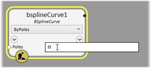
- In the Node Types dialog select the BSplineCurve node and drag and drop it into the Graph view. The node bsplineCurve1 is created.
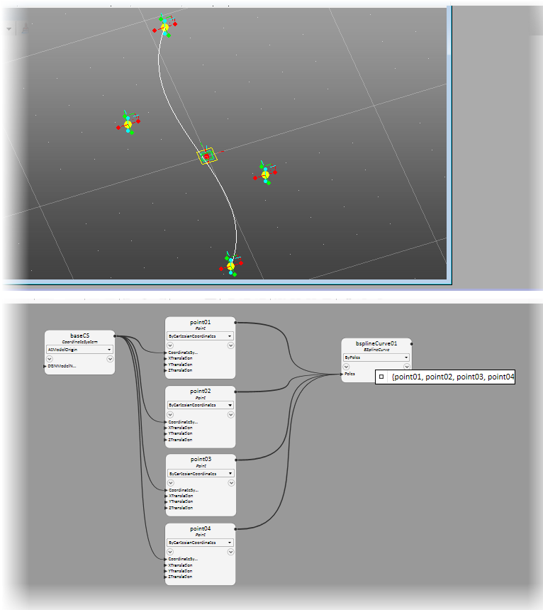
- Click on the techniques drop down menu (the different possible ways to create this feature based on various combinations of inputs), and select the ByPoles technique. There is only one input Poles required to place the curve. The Poles variable expects a List of points to create a BSplineCurve. The syntax for a List in OpenBuildings™ GenerativeComponents is: {point1, point2, point3} where each element is separated by commas between opening and closing curly brackets { }.
- Position the pointer over the Poles input variable. The Poles input expression field appears. Click inside the expression field.
- You can type an expression but you can also select the required pole points. To select existing nodes, hold <Ctrl>, then position the pointer over the points in the model or the Graph view until the name of the feature appears in the input field. Repeating while holding <Ctrl> adds the other points to the poles input.
-
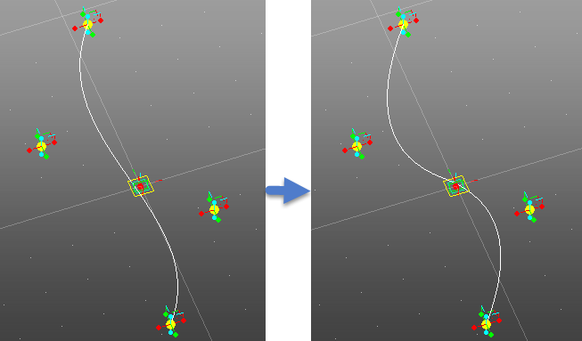
Set the BSplineCurve node's
Order input.
- In the Graph, click the downward arrow icon on the bsplineCurve1 node. A drop down menu appears listing all the inputs associated with the BSlineCurve selected technique (ByPoles).
- Click the "pushpin" icon next to the Order input.
- The Order input is now "pinned" to the bsplineCurve1 node.
- Position the pointer over the Order input until its expression field appears, then enter 3 as the value.
- Record User Changes into Transaction file.